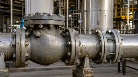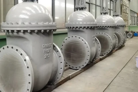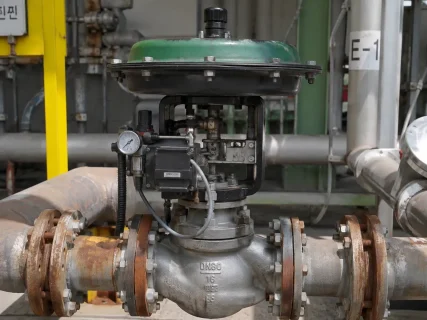

Gate valve vs globe valve are both widely used in industrial piping, but they serve different purposes. A gate valve is generally chosen to isolate a pipeline, while a globe valve is designed to regulate flow as well as provide shutoff.
The distinction matters when selecting valves for systems where pressure loss, flow control and operating conditions all need to be considered. Whether the application is in oil and gas, power generation, chemical processing or water treatment, the right choice starts with understanding how each valve works.
How Do Gate Valves and Globe Valves Work?
Gate Valve Working Principle
A gate valve opens and closes by moving a gate or wedge across the flow passage. Turning the handwheel raises or lowers the gate until it is clear of the passage or seated against the valve seats.
When fully open, the gate moves out of the main flow path, allowing fluid to pass with relatively little resistance. This makes the design useful in pipelines that normally operate in the open position and only need to be shut off for maintenance, repairs or equipment isolation.
Gate valves are available with rising and non-rising stems. The choice often depends on the installation layout and available space. They are intended mainly for fully open or fully closed operation, not for routine flow adjustment. Keeping a gate valve partly open can cause vibration, erosion and premature wear, particularly in demanding services.
Globe Valve Working Principle
A globe valve regulates flow by moving a disc or plug towards or away from a fixed seat. The position of the disc determines how much fluid can pass through the valve, allowing operators to make adjustments during normal operation.
This makes globe valves a common choice for steam lines, boiler auxiliary systems, chemical processing and industrial utility networks where flow rate needs to be controlled.
The body design also affects how a globe valve fits into a piping system. T-pattern valves are widely used for general flow control. Y-pattern designs provide a more streamlined flow path and generally have lower resistance than conventional T-pattern valves. Angle-pattern globe valves turn the flow by approximately 90 degrees, which can be useful when the piping layout requires a change in direction.
Gate Valve vs Globe Valve: Key Differences
Although both valve types can shut off flow, their operating characteristics are quite different.
| Feature | Gate Valve | Globe Valve |
|---|---|---|
| Main purpose | On/off flow isolation | Flow regulation and shutoff |
| Closing mechanism | Gate or wedge | Disc or plug |
| Resistance when fully open | Generally low | Generally higher |
| Flow adjustment | Not intended for prolonged throttling | Suitable for regular flow adjustment |
| Operation | Typically multi-turn | Typically multi-turn |
| Flow direction | Many designs support flow in either direction | Depends on the design and manufacturer’s instructions |
| Typical applications | Pipeline and equipment isolation | Steam systems and process-flow regulation |
For a pipeline that usually runs fully open, a gate valve is often the more practical option because it creates relatively little resistance in that position. Where operators need to change the flow rate during operation, a globe valve is generally better suited to the task.
Using either valve outside its intended function can lead to avoidable operating problems, including excessive pressure loss or premature wear.
Materials, Pressure Ratings and Valve Sizing
The valve body and internal components must be suitable for the fluid, pressure and temperature involved. Material selection should therefore be based on the actual service conditions rather than on the material name alone.
ASTM A216 WCB carbon steel is commonly used in general industrial services. For certain corrosive environments, ASTM A351 CF8M stainless steel may be considered. ASTM A217 WC6 alloy steel is used in selected elevated-temperature applications. The final choice depends on factors such as fluid composition, corrosion risks and operating temperature.
Pressure ratings need the same level of attention. Valves may be specified using PN designations, including PN16 and PN40, or ASME pressure classes such as Class 150 and Class 300. These systems are not directly interchangeable. Always check the applicable pressure-temperature rating for the selected material and valve design.
Connection details can also affect whether a valve is suitable for an existing installation. Common end connections include flanged, butt-weld and socket-weld designs, depending on the valve configuration. For replacement work, check the face-to-face dimensions, connection type, flow capacity and pressure rating. Matching the nominal pipe size alone does not guarantee that a replacement valve will fit or perform as required.
Common Gate and Globe Valve Designs
Both valve types are available in several configurations. Some are intended to suit restricted installation space, while others address particular pressure, temperature or sealing requirements.
| Valve design | Typical application or benefit |
|---|---|
| Non-rising stem gate valve | Useful where vertical clearance is limited |
| API 600 gate valve | Steel gate valve designed to meet the applicable API 600 requirements |
| Resilient-seated gate valve | Provides tight shutoff in suitable water-service applications |
| Pressure-seal gate valve | Used in selected high-pressure, high-temperature services |
| Bellows-seal globe valve | Uses a bellows assembly to help limit external leakage through the stem sealing arrangement |
| Y-pattern globe valve | Offers lower flow resistance than many conventional T-pattern designs |
| Angle globe valve | Changes the flow direction by approximately 90 degrees |
| Pressure-seal globe valve | Designed for selected high-pressure applications |
The installation and service requirements should guide the choice between these designs. A non-rising stem gate valve, for instance, may be useful where there is limited headroom. A bellows-seal globe valve may be considered where reducing external leakage through the stem area is important.
Before placing an order, buyers should check the design standard, material specifications, pressure-temperature ratings and manufacturer’s documentation. Similar valve types can have different operating limits depending on their construction.
European Standards and Industrial Applications
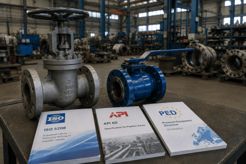
Valve specifications for European projects often refer to EN standards, alongside relevant API or ASME requirements. The standards selected depend on the valve type and the project’s design, dimensional and testing requirements.
Some commonly referenced standards include:
- EN 1984: Covers steel gate valves.
- EN 13709: Covers steel globe and globe stop-check valves.
- EN 558: Specifies face-to-face and centre-to-face dimensions for metallic valves.
- EN 1092-1: Covers circular steel flanges and their associated PN designations.
- EN 12266-1: Specifies pressure testing requirements for industrial valves.
The Pressure Equipment Directive 2014/68/EU may also apply to qualifying pressure equipment, depending on its classification and the relevant conformity-assessment requirements.
These standards provide a basis for specifying valve design, dimensions and testing. They do not, by themselves, establish that a particular valve is suitable for every application. The operating conditions and project requirements still need to be checked.
In practice, gate and globe valves are used across several European industries. Manufacturing and chemical plants rely on them in process lines and utility systems. Power stations use suitable configurations for steam services, equipment isolation and auxiliary systems. Port terminals and storage facilities also require valves to manage pipeline flow and isolate equipment.
The choice between a gate valve and a globe valve comes down to the job it must perform and the conditions under which it will operate.
How to Choose the Right Valve
Start with the operating requirement. If the valve is mainly needed to isolate a pipeline, a gate valve is generally a suitable option. If the process requires operators to adjust flow regularly, a globe valve is usually the better starting point.
Before selecting a model, consider:
- Operating conditions: Identify the process medium, pressure and temperature, including variations during startup and shutdown.
- Material compatibility: Check that the body, trim and sealing materials are suitable for the fluid and service environment.
- Flow requirements: Establish the required flow capacity and, where relevant, the degree of control needed. Consider the pressure drop across the valve.
- Installation: Confirm the available space, valve dimensions, end connections and operating arrangement.
- Maintenance and automation: Consider access for inspection and servicing, as well as actuator compatibility if automated operation is required.
- Standards: Check the applicable design, testing and project specifications.
For replacement projects, dimensional compatibility deserves particular attention. Comparing the proposed valve against the existing installation can help identify differences in face-to-face dimensions, end connections and pressure ratings before work begins.
Where pressure, temperature or fluid conditions are demanding, general selection guidance is not enough. The final decision should be checked against the engineering specification and the manufacturer’s technical data.
Gate and Globe Valves from Valves Only Europe
Valves Only Europe offers industrial gate valves and globe valves for a range of piping and process applications. The appropriate configuration depends on the service conditions, installation requirements and specifications of the project.
When requesting a quotation, provide the valve size, pressure rating, operating temperature, process medium, material requirements, end connections and applicable standards. Details about the required valve design and operating conditions will also help narrow down suitable options.
Clear specifications make it easier to assess the application and identify a valve that meets the installation’s technical requirements.